Skip to content
Details

Custom Electronics Insert Boxes

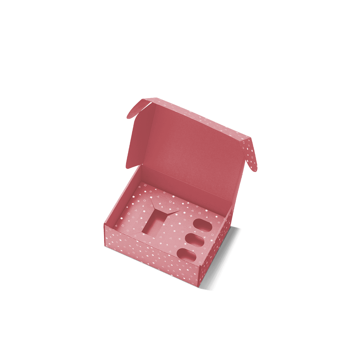
Organise devices, cables and small components in a clear opening order with fitted paperboard supports shaped around weight, access and delicate product areas.

Free Design Support

Clear Pricing

Flexible Quantities

Unlimited Customization

Premium Materials

Offset Precision

Free Shipping

Quick Turnaround

Custom Electronics Insert Boxes for Devices and Complete Sets

Custom Electronics Insert Boxes should keep the main device steady, separate every accessory and make the opening order easy to understand. The insert and outer box must be planned together rather than treated as two unrelated parts.

A complete electronic set may contain a device, charging lead, wall adapter, mounting parts, instruction card and warranty booklet. Placing everything in one cavity can allow hard parts to collide. It can also hide the main item beneath cables or paperwork.

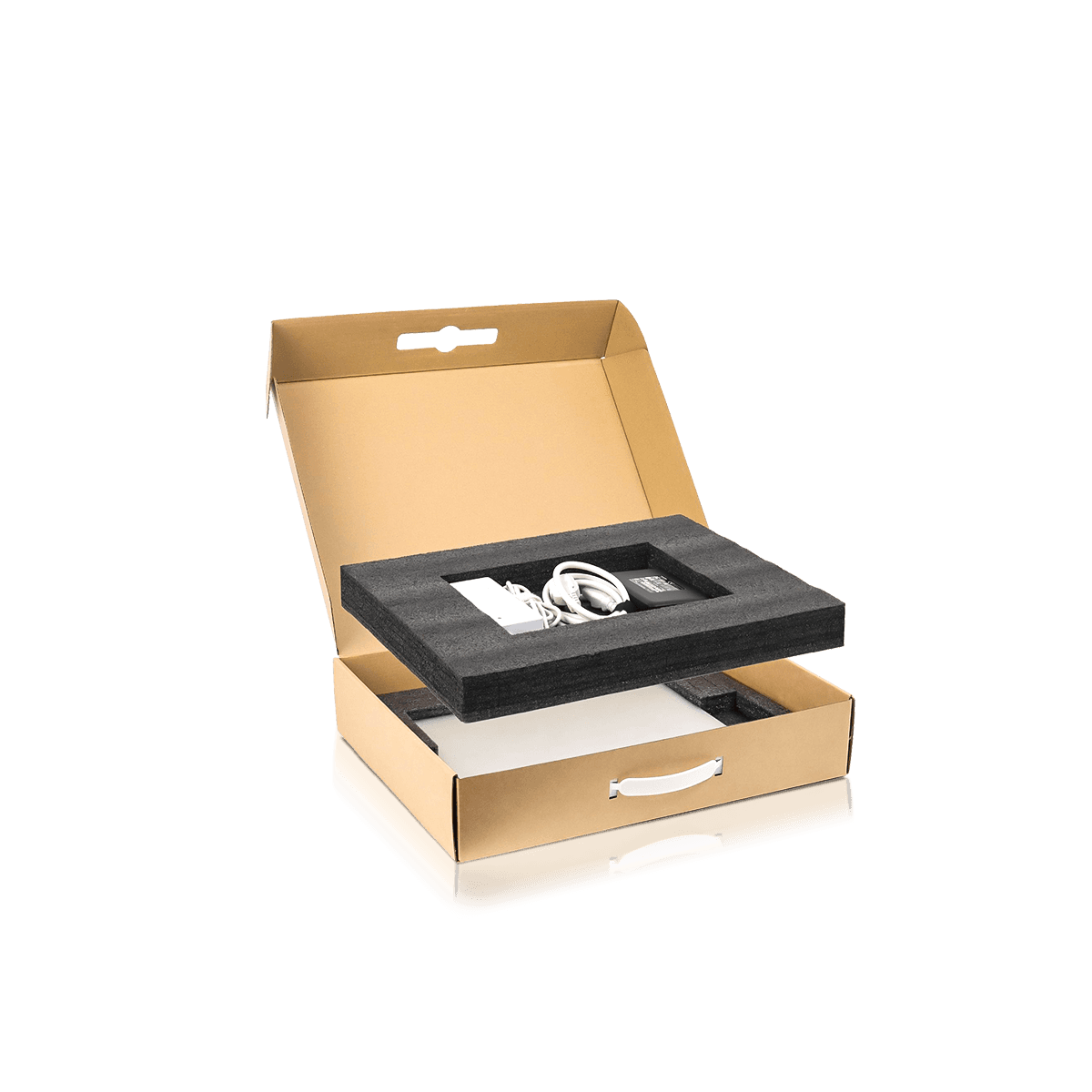
A fitted insert gives each component a defined position. It can raise the device into view, keep plugs away from finished surfaces and create a lower level for supporting items.

Products across Custom Electronics Packaging often share this need, but the insert must still reflect the exact weight, shape and opening sequence of each device.

Single devices with one accessory

A simple paperboard cradle can hold the device while a side pocket contains the charging lead or booklet.

Multi-part electronic sets

Layered trays and compartments can organise adapters, receivers, mounts and spare pieces without covering the main product.

Retail and presentation boxes

The insert can centre the device behind a window or place it at a consistent height for a neat shelf presentation.
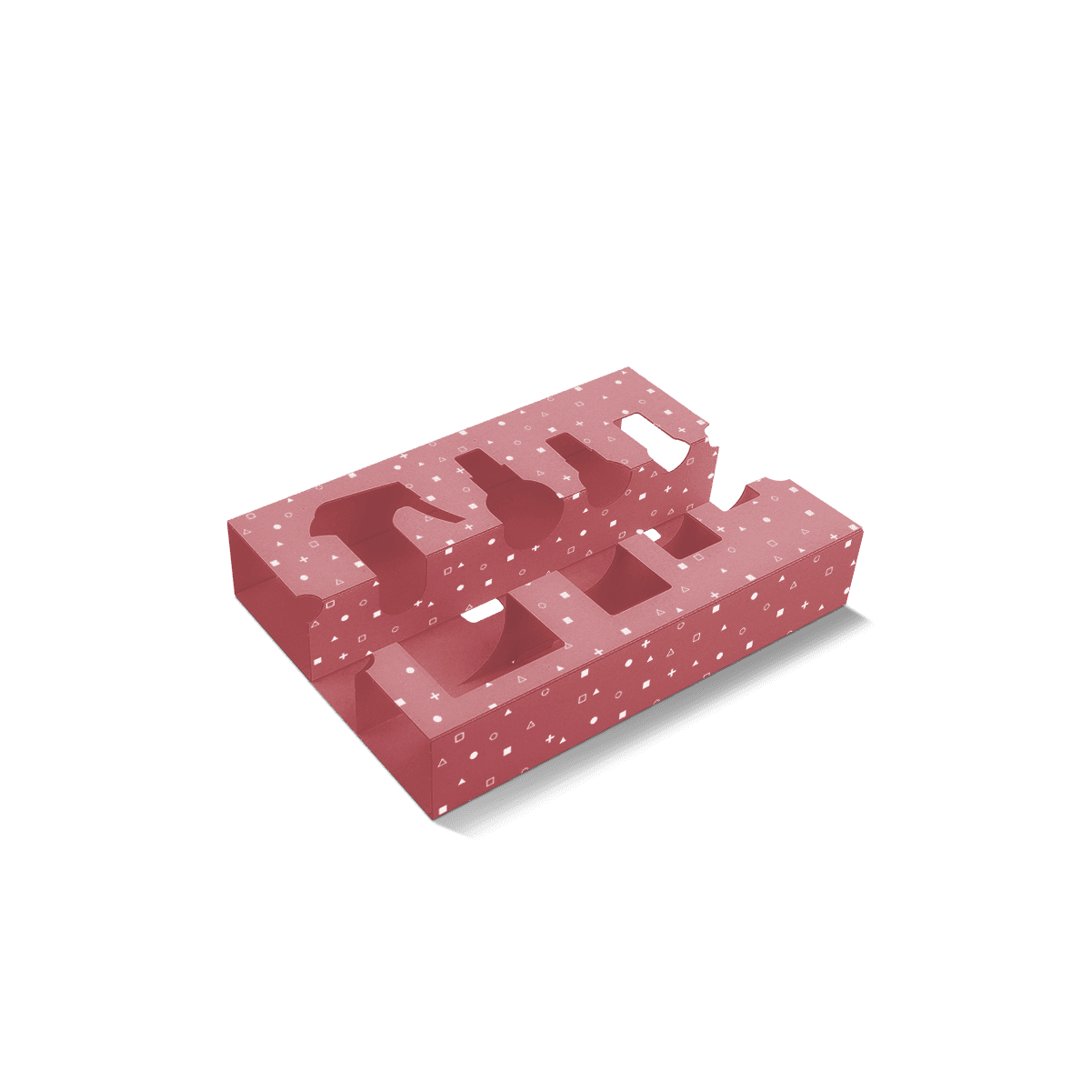
Plan the Opening Order Before Drawing the Cavities

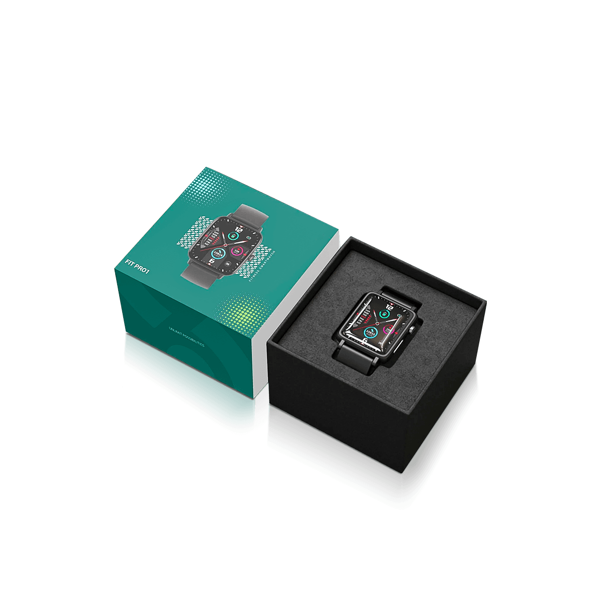
The best insert layout begins with what the customer should see first. In most Custom Electronics Insert Boxes, the main device should appear before the cable, adapter and paperwork.

Opening order also affects loading. Staff need a clear sequence that places every item without lifting or removing parts already positioned in the box.

Place the main device on the first level

The first tray should show the product clearly and give enough access for safe removal. Small accessories can sit beside it when they do not distract from the device.

Move supporting items below

A raised platform can create space beneath the main tray for cables, booklets and adapters. The lower items should not push upward when the box closes.

Keep setup cards easy to find

A narrow pocket under the lid or beside the insert can hold instructions flat. Avoid placing paperwork where it can fold into the device cavity.

Support Strong Areas and Clear Delicate Features

Custom Electronics Insert Boxes should carry the product at firm case edges, stable bases or other approved contact points. Screens, lenses, ports and raised controls should remain clear.

Start by marking the areas that can accept support. Then note every part that should not touch the tray or lid.

Leave space around screens and lenses

A device with a glass face or lens needs enough height above it. The upper box panel should not rest on the delicate surface when closed.

Clear ports, buttons and switches

Insert cut-outs can leave open areas around controls and connection points. This also helps staff check the correct product orientation before closing the box.

Avoid pressure on sensor areas

Raised sensors and charging contacts may need an open centre beneath the device. A ring-shaped support or side cradle can hold the case perimeter instead.

Tell the packaging team when an item must remain inside an approved protective bag, sleeve or tray. The insert dimensions can then allow for that added layer.

Choose Paperboard or Corrugated Support by Weight

The insert material should suit the device weight, cavity depth and outer box. No single material is right for every electronic product.

Paperboard gives a clean surface and folds into detailed cradles, bridges and pockets. Corrugated board adds fluted strength for heavier devices and deeper supports.

Paperboard for compact electronics

Folded paperboard can support sensors, smart devices, mobile accessories and small control units. It works well when the product has a regular shape and firm contact points.

Corrugated board for denser items

Corrugated supports can suit power units, larger controls and electronic tools. End cradles or folded rails can spread the weight across the box base.

Layer pads for stacked components

Flat pads can separate product levels or several retail cartons inside a shipping case. They should not replace a fitted cradle when individual devices could move.

Complex inner layouts often use the same structural thinking found in Custom Inserts and Dividers, with each fold serving a specific support or separation role.

Size Every Cavity for Access as Well as Fit

A cavity that matches the exact product outline may still be difficult to use. Custom Electronics Insert Boxes need enough tolerance for loading, removal and normal production variation.

A very tight insert can scratch coated surfaces or make staff push the product into place. Too much clearance can allow movement.

Add finger access where it is needed

Finger notches, open corners and paper pull tabs can make deep or flat devices easier to remove. Access should not rely on pulling a cable or connector.

Allow for surface wraps

Protective films, paper wraps and approved bags change the working dimensions. Measure the item as it will enter the final box.

Check the highest point

Buttons, dials and curved covers may sit above the main device body. The box depth should follow the tallest point in the loaded layout.

Give Cables and Adapters Their Own Compartments

Cables and plugs can damage the presentation when they sit loose against the device. Custom Electronics Insert Boxes should control both the main cable coil and its connector ends.

A cable pocket can sit beside the device. A stepped insert can hide it beneath the main tray. Wall adapters and travel plugs may need separate cells because of their weight and projecting pins.

Use the real cable coil

Measure the cable after it has been prepared with its paper band or tie. A sample coil wound more tightly than the production method can lead to an undersized cavity.

Keep plugs away from finished faces

Metal connectors and plug pins should not rest against screens, coatings or soft surfaces. Paperboard walls can maintain separation.

Make missing parts easy to notice

Open accessory cells allow staff to see whether every cable, adapter and receiver is present before the box closes.

Match the Insert to the Outer Box Structure

The insert depends on the outer box for side support, closure and presentation. Custom Electronics Insert Boxes should therefore be developed as one complete structure.

Light devices often sit well inside Custom Folding Cartons and Tuck Boxes. A folded insert can lock against the carton walls and lift the product into view.

Premium devices and launch sets may use Custom Rigid Boxes. A rigid lid-and-base or drawer box can hold a deeper tray and reveal accessories in stages.

When the printed outer carton is central to product information, Custom Electronics Boxes can combine clear model details with a fitted internal layout.

Prevent the insert from shifting

The finished insert should sit securely against the box walls. An undersized tray can move even when the device fits well inside it.

Check closure pressure

The upper panel or lid should close without pushing the device, cable or paperwork down into the tray.

Keep windows aligned

When the outer box includes a window, the insert must hold the visible product area in the correct position throughout display and delivery.

Make Hand Loading Faster and More Consistent

A clever insert is not useful when it takes too long to assemble or creates uncertainty at the loading table. Custom Electronics Insert Boxes should have an obvious folding sequence and clear component positions.

Reduce unnecessary folds

Each fold should create support, separation or access. Extra tabs can slow assembly without improving the finished structure.

Use one clear loading direction

The device should enter the cavity in a set orientation. Cables, adapters and cards should follow in an order that does not require earlier items to be removed.

Create a loading reference

A photograph or simple diagram of the approved layout can help staff position every component consistently. It is especially useful when several similar device versions share one outer box.

A consistent loading process also makes missing or incorrect components easier to identify before sealing.

Use Colour and Print Inside With Purpose

Paperboard inserts can carry print, but decoration should not make the layout harder to understand. The most useful inner print supports loading, identification or the customer experience.

Label accessory positions

Short labels such as “charging cable” or “adapter” can help when several small parts sit in similar cavities.

Use colour to separate product levels

A contrasting tray can make the main device stand out. Related products can share the same visual treatment even when the cavity shapes differ.

Keep instructions short

A setup step or support message can sit beneath the device or inside the lid. Longer technical instructions are usually easier to read on a separate card or booklet.

The Customisation options can align the outer print, inner tray and finish without covering the practical purpose of the insert.

Test the Fully Loaded Insert Before Production

A sample should contain the real device and every included component. An empty Custom Electronics Insert Box cannot show tray flex, cable pressure or how the total weight affects the base.

Close the loaded sample and turn it through the positions it may face during storage and delivery. Reopen it and check whether any part has shifted.

Check movement between compartments

Cables, adapters and mounts should remain within their cells. Small parts should not pass beneath the main tray.

Inspect every contact point

Look for rub marks, pressure lines or areas where a connector touches the device. Adjust the support before final approval.

Repeat the loading process

Load and unload several samples. This can reveal tabs that catch, cavities that are too tight or parts that take too long to place.

A 3D mockup can confirm general dimensions and artwork. A physical sample is more useful when the device is heavy, the tray has several levels or fit tolerances are narrow.

Manage Several Devices Without Forcing One Insert

A related product line can share one visual identity while using different inner structures. Custom Electronics Insert Boxes should change when product dimensions, weight or accessory positions change.

One outer box may sometimes work across similar devices. In that case, separate insert versions can control the fit. This only makes sense when the shared outer dimensions do not create excess material or weak presentation.

Separate artwork changes from insert changes

A new device colour may need revised print only. A moved port, larger adapter or thicker case may require a new cavity.

State quantities for each insert

A total order may contain several tray designs. Give the amount for each device, artwork and insert so pricing reflects the real production split.

Keep approved files together

Store the outer dieline, insert drawing, artwork and loading image under the same version name. This helps prevent the wrong tray being used with a similar device.

Send the Complete Layout for an Accurate Quote

A useful quote for Custom Electronics Insert Boxes needs the outer box requirements and every item that will sit inside it.

Send:

  • Device length, width, height and weight
  • Photos from several angles
  • Firm support areas and features that need clearance
  • Cable, adapter, mount and receiver dimensions
  • Prepared cable coil sizes
  • Cards, manuals and warranty booklet dimensions
  • Intended opening order
  • Quantity for each device and insert version
  • Retail, gifting or delivery use
  • Preferred outer box and insert material
  • Artwork status and required date

A simple sketch can show where each component should appear.

Send the full set through Get a Quote so Custom Packly can assess the outer box, insert architecture and version split together.

Process

How it works

Simple steps from idea to delivery

01

Tell Us Your Specs

Custom packaging boxes

Tell Us Your Specs

Provide size, quantity, printing, and finishes.

02

Get a Fast Quote

Custom packaging boxes

Get a Fast Quote

Instant transparent pricing, no hidden fees.

03

Design and Approval

Custom packaging boxes

Design and Approval

Artwork checks, revisions, and final sign-off.

04

Produce

Custom packaging boxes

Produce

Expert manufacturing to meet deadlines.

05

Ship to Your Door

Custom packaging boxes

Ship to Your Door

Hassle-free, flexible delivery options.

Start Your Custom Packaging Quote

Share your product details, dimensions, quantity and artwork needs. We’ll help choose the right packaging style and send a clear quote.